Enter the search phrase
At Robotec.ai, we focus on building simulations for robotics driven by the modern Robot Operating System (ROS). We found a great fit for that in Open 3D Engine, which we actively develop for purposes of robotics through our open-source activity within The Linux Foundation as well as commercial, customer-driven projects.
Last month, we joined the yearly international conference, ROSCon 2023, which was held in New Orleans. Between our gold sponsorship, the Open 3D Foundation booth, and a talk by Adam Dabrowski, we had a terrific opportunity to highlight the unique strengths of O3DE and share why we use it to build our simulation platforms.
For this purpose, we built an open-source demo project of multi-robot simulation in a large warehouse, featuring both robot manipulator arms and Autonomous Mobile Robots (AMRs). The demo is yet another fruit of our amazing collaboration with the AWS O3DE team.
If you have not seen a video of the demo yet, we highly recommend you spend 2 minutes to watch it now.
We have received amazing feedback, and many people were inspired to build with O3DE. This blog post aims to help you with that!
An effective way to start is to get your first small project going. There are documentation pages on important topics such as configuring, building, and importing your robot into O3DE.
You might also want to run one of the tutorials coming with three robotic project templates. They can help you learn how to integrate your simulation with navigation and robot arm manipulation stacks, nav2, and MoveIt2. But how do we build a more complex simulation? How do you approach the design, get started, build your scene, and integrate all the pieces? Our journey begins with the first step.
Having built an Agriculture demo last year and a Consumer one previously, we decided to take on the case of robotized warehouses, which synergize well with what we are building for our customers.
The idea was to build something impressive, not seen before, and we knew that we could make it happen with O3DE. Finding the right intersection of ambition and resource efficiency is never easy, but you can reduce the risk somehow by including an intermediate goal that doubles as plan B for the delivery.
Our plan A was the demo you can see and build. We succeeded, although not without a crunch in the last couple of weeks. 12 robot arms and 24 AMRs were orchestrated over 9000 square meters. Our plan B was one-third of that: 4 robot arms, 8 AMRs, and 3k sqm.
We knew we wanted robot arms, AMRs, and palletizing. But how would our virtual scene look like? Which robots to select, and how to make them work together?

Source: AstraZeneca Palletizer
We looked at real-world recordings and pictures of robots operating autonomously in warehouses. Even though the demo is not customer-driven but rather a showcase of the engine’s capabilities, having it clearly illustrate a real-world application is essential. Our primary goal with simulation is to help solve real automation problems. While no videos showed palletization and delivery at the scale we envisioned, they served as great reference points for the scene design.
Now, it was time to illustrate the concept of the scene. Have fun with it! It really does not need to be much, as our first drawing clearly demonstrates:

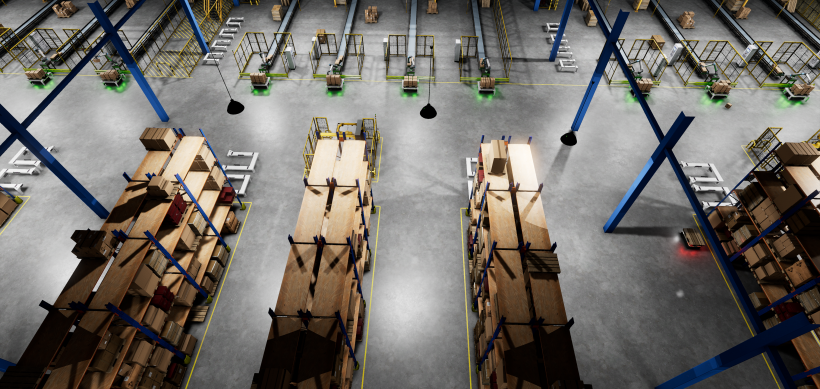
To kickstart our demo and build a prototype scene for testing, we used resources from O3DE robotic templates available to everyone. Elements such as warehouse racks, boxes, and conveyor belts were all used to initialize our simulation environment. Templates are meant to do exactly that: help developers to start quickly. After placing warehouse-themed models on the scene, our prototype environment was ready.
Since our demo was to be displayed at ROSCon, we decided to prioritize robots that are well-recognized in the ROS community and consider current sponsors of the conference for extra interaction.
We opted to use OTTO Motors by Rockwell Automation OTTO 600 and Universal Robots UR 20.

The community is supportive of such projects, and when we reached OTTO Motors, they provided an STL mesh which was an effective way to kickstart 3D modelling work. Similarly, while the UR 20 description package had not been released at this point, we communicated our need for it, which contributed to getting it sooner. We recommend engaging with companies and using shared or public resources.
To make sure our robots look and behave like their real counterparts, we studied recordings of these robots in action. Since we were not going to simulate their robotic stacks and sensors, our choice of sensors was guided by what was needed to make it all work.
Simulate only what you need.
Time for some creative work with 3D models. The process can be quite time-consuming, but it is a crucial step in the creation of a realistic simulation environment.
We also had to decide which of the models we needed to create from scratch and which we would only visually improve based on public resources, such as the robot description package for UR 20. If the base model is too simple, we need to improve detail based on pictures and recordings. On the other hand, if it is unnecessarily complicated, such as when the mesh contains all the screws and cables, it is sometimes better to use it as a reference and create a new one. In this way, we have a bigger influence on the appearance of the model and its complexity that affects performance.

An additional motivation for creating a new model was that we were free to share it with the community. Since the license for ready models typically prevents this, buying such resources was not a good option.

We typically approach the modeling process in two stages: mesh modeling and texturing. For the meshes, we used Blender, a popular and powerful tool. It is free and open source. Blender also supports working with textures, but for this purpose, we used Substance Painter and Substance Designer instead, a common software used in the 3D modeling pipeline for games and simulations. It helps to create high-quality materials in a shorter time.
For better performance, finer elements of the model can be simulated with a texture. The engine uses Physically Based Rendering (PBR), shading, and rendering techniques that simulate how light interacts with material properties. Several types of maps, such as base color, metallic, roughness, and emissive, are used to achieve a realistic material appearance. A good practice is to create a detailed model and its simplified, low poly version. You can then use the high poly model to create texture maps by baking detailed elements on them. To ensure the texture displays correctly on the model, it is essential to unfold the mesh. This technique is called UV unwrapping, and it involves translating the surface of a 3D model into a 2D coordinate system. Finally, adding a simplified collider shape for detailed models also improves performance.
The last step is to export the 3D model in a format readable by O3DE. We used FBX, a common format for game and simulation engines and 3D modeling tools. It includes information about mesh, textures, and animations.

Building the simulation scene is more than just arranging the models spatially. For the demo, we considered three main aspects:
When building such a scene, be prepared to make some trade-offs. Models with more details and larger textures typically make things look better, as do lights of high quality and other settings such as reflections, environmental lights, and camera effects. There is a balance point to find between performance and looks.
The easiest way of scaling up the scene is to build it out of prefabs, which can be easily duplicated and combined. This approach does not necessarily scale up in terms of performance; for example, integrated, big meshes perform better than many separate objects. To achieve a reasonable level of diversity, these big meshes for rows of warehouse racks were developed in a few variants with different permutations of objects. In this case, you need to balance convenience of use with performance. A good rule of thumb is not to optimize prematurely while still building the scene.
The warehouse building is itself a prefab and was created in a modular way. Each wall can be disabled using the override system. We linked such prefabs together to create a larger warehouse. This trick does not work so nicely in the case of lights. The best looks can be achieved with a large number of lights with high-quality shadows and diffuse lightning. We used Diffuse Probe Grid (DPG) component, which works wonders when properly configured. For some areas, we included multiple DPGs to increase quality.
The next step is to add details. Aside from a selection of smaller models, we used decals to add floor lines and other painted elements. These are lightweight but make a difference when it comes to looks!

Now, it was time to add more liveliness to the scene by introducing human workers and wrapping stations, which were truly relevant to the use -case.
Aside from 3D modelling work, human models need animation. One way to achieve it is to create a skeleton and animation that will move it. This digital skeleton consists of bones and joints inside a character or object. Skeleton is typically bound to mesh vertices in a process called skinning. The output rig enables moving models through prepared animations. The animation process involves setting keyframes at selected points in time, which defines the position of elements in space. The animation program interpolates these positions to smooth the transitions between them.

Now, it is time to teach our model how to walk with some awareness of its surroundings. Our goal was to simulate multiple inspectors walking around between different areas. We used Recast Navigation Gem, which allowed us to efficiently generate a map for our inspector to find paths and move freely on our scene. To simulate inspection, we added a feature to allow navigation between multiple points of interest with idle time at each point. We also added an interface to limit the map calculation to a certain region around the points of interest for better performance.
This solution is simplified, as the map is calculated only at the start of the simulation. Our inspectors will not notice moving AMRs. Fortunately, robots are not as distracted by mobile devices and will avoid collisions thanks to the ROS 2 navigation stack working with their lidar sensors.

The human inspector, including meshes, textures, animations, and implementation of navigation, is released as a separate O3DE Gem under Apache 2.0 / MIT dual license, which makes it easy to integrate into other projects.
In some reference videos from warehouses, we noticed machines for wrapping packages loaded on pallets. We decided to model it to enhance our demo visually and make it more interesting. At the same time, it was not important to simulate the process, so we opted for a scripting / animated approach.

The wrapping process employs a scripting approach and triggers reminiscent of events in real games, such as a surprise attack on the main protagonist. In our simulation, when a robot’s payload enters a collider, it initiates a sequence of events:
The underlying logic is encapsulated in a custom component residing in the project’s Gem. This component highlights the effectiveness and elegance of EBus communication in O3DE. The FoilWrapperComponent communicates with four Gems: PhysX, EmotionFX, Atom, and ROS 2.
You might face challenges developing scripted events impacting physics, as code bugs can lead to unexpected behavior. For instance, creating a fixed joint between payloads on two separate robots may result in an “explosion.” Debugging such events is intricate due to a lack of robust debug output. Integration with Nvidia PhysX Visual Debugger proves invaluable in such scenarios. This tool enables a detailed review of all simulated physical primitives and their parameters frame by frame, making debugging unexpected behaviors in physics simulations more manageable.
The awesome foil wrapper model, including the animation, was generously provided by https://github.com/shawstar.
ROS 2 is a great enabler for most of our work. Having the middleware, control, and behavior packages for our robots helps us to build much faster. Of course, you always need to pick your algorithms, validate them in your setup, configure them, and fine-tune them.
One of our main challenges was to solve the problem of simulated palletization. We needed something to stack 18 boxes on top of each pallet as they were brought into position next to robot arms by AMRs.
MoveIt2 is an open-source software ROS 2 framework dedicated to robot manipulation tasks, which finds applications in areas such as collaborative or service robotics. For the problem of patterned, homogenous items palletization, applying MoveIt2 might be considered overengineering, but we picked it as our solution because the focus was to show the ease of integration with ROS 2 tools.
The palletization task was divided into the following steps:
For the first step, you need to apply a vision system. Building box and pallet detectors based on computer vision was outside the scope of our demo. Instead, we developed a custom ground truth vision system, which means that we relayed on knowing the exact positions of every object in the simulation.
Our ground truth vision component coexists with the camera sensor component and makes use of its extrinsic and intrinsic parameters to create a PhysX shape out of the camera’s frustum. We used this shape to perform a shape-cast query to the PhysX scene, getting all simulated physical bodies that overlap with it. After simple processing, our component publishes detections as a couple of standard ROS 2 vision messages: Detection3DArray and Detection2DArray. We proceeded to apply our new component, IdealVisionSystem, to detect the pose of a box on the conveyor belt as well as pose of the pallet.
If you wish to plug in your vision pipeline instead, replace the ground truth component with a ROS-side detector based on RGBD data from the camera, working with your choice of a novel ML pipeline or Random-Consensus approach.

The early stage of development, example, planning scene in MoveIt2
All the following steps require planning and execution of trajectories, which is what MoveIt2 planners are for. However, the application of MoveIt2 to our palletization problem turned out to be quite challenging.
The role of the planner is to find a safe path from the robot effector’s current position to the target position while keeping a number of constraints, such as joints limits, avoiding collisions, and optimizing metrics. Having prior experience with PLCs and industrial robots, we found default configuration employing CHOMP and OMPL planners particularly challenging to use due to being unpredictable. Four robotic arms in the simulation were given the same task. Three found a completely different plan, and one of them failed to find a plan.
We had limited success with the MoveIt Task Constructor, which allowed us to break complex tasks into smaller pieces and chain them together. However, even with smaller planning tasks, making the experience more predictable, planning failures were still rampant. We tasked 12 robot arms to stack a nice grid of 6×3 boxes, and only one robot finished it completely.
Finally, we came across Pilz Industrial Motion Planner, a simplified, robust, and consistent planner available for MoveIt2. While it has a limited feature set and is unable to avoid obstacles, it turned out to be very reliable. Programming a robot’s movement with this planner is a similar experience to programming a CNC machine or industrial robot, and we found that a combination of MoveIt2 with Pilz Industrial Motion Planner solves our palletization problem.

Now, it is time to make our AMRs move pallets to delivery and return for more. Selecting the ROS 2 navigation stack for the job is an obvious choice. This is what Nav2 is for: an all-in-one navigation framework for ROS 2. Nav2 and our additional custom packages form the “brain” of each AMR.
Our custom packages include:
A custom O3DE component that manages the scene paths that the AMRs take was also added, along with its specific message package called lane_provider_msgs.
AMRs follow paths provided through otto_deliberation using navigate through poses, which allows for fine-grained navigation goals. The navigation stack will go to the first pose on the path using the shortest distance and continue to follow the predefined path. It detects obstacles and navigates around them.
It proved to be problematic for some tight spaces, and we prepared blind_path_follower to handle these. In the beginning, this package was truly blind. The only known information it had was the real position of the robot and the sequence of points that define a path. It turned out not to be sufficient as the robot would miss its path when turning or when the start position was not exactly on the start of the path. To solve this, we made the robot slow down on turns or when the distance from the set path exceeds the predefined threshold. Each robot also became equipped with a custom component for detecting if another AMR was in front of it. It helped to stop the AMR if its path was obstructed, resulting in queueing behavior.
The central robot reasoning package is otto_deliberation. Its configuration includes assigned work lanes and a set of tasks that are associated with paths. It gathers the path’s poses from the simulation scene using a custom ROS 2 service and keeps track of the state of the robot’s cargo, which is required for some tasks such as loading. Each robot can request or release the lock for a given path through a service call to global_path_lock, which handles locking through a simple set of strings.
As you can see, preparing such orchestration for a demo is quite different from building a simulation for validation of the real application. In the latter case, the robot software stacks are already there, and you need to integrate your simulator with them.

As in any project complex enough, integration is a process where a lot of things can go south. Things tend to cause problems when put together, even if they worked in separation. It is nothing new to say that modern ROS is a good solution for building large systems, mainly because of a choice of packages, natural encapsulation, separation in the nodes, and communication.
However, O3DE played no lesser role in the success of simulating massive scenes with multiple agents. Having a toolset capable of creating AAA games serves well to create and run large open worlds with hundreds of actors. Direct integration of O3DE with ROS 2 and design choices specifically for ROS developers really paid off.
The integration of the whole simulation was a challenging task and took a number of iterations. Most problems were caused by robots interfering with each other’s plans, such as when our first approach to robot deliberation worked perfectly with one robot but degraded with multiple due to a more complicated state logic.
Our belief is that challenging your navigation and fleet management system in simulated environments can provide an opportunity to make the whole implementation process smoother, safer, and more cost-effective.
Having a working, smaller scene with 12 robots was a big step towards our goal. Now, it was time to scale it up three times. As expected, our initial performance was not great.
It took some profiling to identify causes. Surprisingly, the way we used to broadcast dynamic transforms was one of the key issues. It is way more efficient to gather transforms from a single frame into a vector first and publish once per frame. The solution was simple enough and is now included in ROS 2 Gem.
The other issue was conveyor belt physics implementation. Spawning and de-spawning at both ends is not efficient. However, in this case, we did not manage to get a proper solution in time and had to use workarounds such as shortening the operational part of the belt significantly.
The scene was also optimized for performance, using techniques previously described in the text.
To handle lots of lidar sensors, we used Robotec GPU Lidar Gem, which handles such loads with ease.
The final part was optimizing our ROS system. We used composable nodes, fine-tuned DDS settings for larger traffic, and batched launch files to avoid big initial computation spikes. Finally, we ran all our stacks on a separate machine connected through an ethernet cable.
Our threshold of 30 fps on our local desktop machine was finally reached!

Capturing recordings of our demo running proved to be quite an adventure. For optimal quality and frame rate, we opted for an external frame grabber – a nifty device with HDMI input that enabled us to delegate the video recording process to a separate computer. We did this to ensure a smooth and high-quality video and prevent any slowdowns on the computer running the simulation.
Fluid camera movement within the simulation was a critical aspect of our video appeal. While the standard O3DE provides ample resources for developing and testing the simulation, we took an unconventional route to enhance our control over the camera movement. Typically, you would use predefined splines to control camera movement, but we needed to record over an hour of video to show the time-lapse of our simulation and to have more control.
In a bold move, we integrated an RC controller commonly employed for steering RC planes, cars, and drones. This controller, equipped with a trainer mode that emulates a joystick, set itself apart with numerous switches, knobs, and four main axes. To make this work seamlessly, we developed a straightforward camera controller, essentially an oversimplified drone control simulation, which effectively mapped inputs from the RC controller.
With these final tweaks in place, we successfully resolved the last remaining challenges and recorded a demo video that captured the essence of our robotized warehouse simulation.
I hope you enjoyed reading about our ROSCon demo project and learned something from this article. If you are inspired to build with O3DE, let us and the entire community know what you are building!
Join the O3DE Discord and share your projects in simulation or showcase channels.
Special thanks to the AWS For Games team, who were instrumental in making the project happen and supported us thoroughly!
Adam Dąbrowski, Artur Kamieniecki, Jan Hańca, Michał Pełka, Paweł Budziszewski, Piotr Jaroszek, Piotr Rząd
Special thanks to other demo builders, including:
Our engineers: Paweł Liberadzki, Michał Wasilewski.
Interns: Anna Fąferek, Kacper Lewandowski, Antoni Puch.
3D modelers: Filip Dragon, Łukasz Kawecki, Monika Syruć, Michał Kapica, Tomasz Pasterak, Roman Pietrashko.
AWS for Games: Starr Shaw.
Want to stay updated with our projects? Follow our LinkedIn page!
You can also leave us a star on GitHub to help others find the project.